For all technical questions. VIEWABLE without login, you need to register (free) to be able to post a question.
-
Cameron_benn210803
- Full Member
- Posts: 12
- Joined: Mon Nov 18, 2024 10:59 pm
Post
by Cameron_benn210803 » Tue Jul 08, 2025 5:07 pm
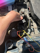
Having trouble with using the diagnostic port I have done what the forum says to do but it still does not work looking for help thanks
-
jrh
- Full Member
- Posts: 1087
- Joined: Thu Sep 20, 2018 3:08 pm
- Been thanked: 46 times
Post
by jrh » Tue Jul 08, 2025 7:37 pm
Double check LED and resistor connections.
-
Micron
- Site Admin
- Posts: 3531
- Joined: Thu Sep 06, 2018 6:08 pm
- Location: South Norfolk
- Has thanked: 62 times
- Been thanked: 96 times
Post
by Micron » Wed Jul 09, 2025 9:25 am
As said on Facebook,
You need a 12v LED.
Your yellow strap is correct, with the GND port on the left and TBS on the right side of the strap.
the wiring for the lamp is wrong, it is currently between TBS and nothing? Once you have a 12v LED the positive side (red if you connect it to the positive leg of the LED) goes to the FBS and the other side, yellow in your case goes to GND ( the same ground as the strap on the left.
take another look at the diagram and you will see your error.
Admin and Owner of this fine club

Location : South Norfolk
Who is online
Users browsing this forum: No registered users and 274 guests
